Build log: Vortex Pok3r hotswap mod
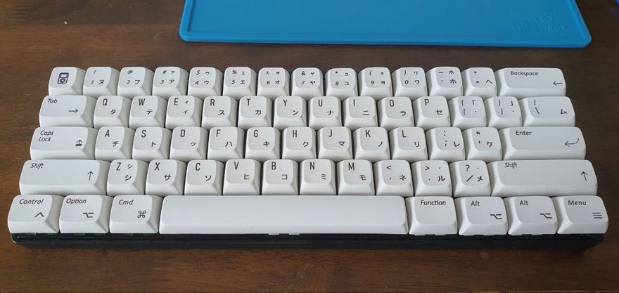
My first mechanical keyboard is a Vortex Pok3r, which I've had since 2015. It's a 60% keyboard — so it doesn't have arrow, function, navigation and numpad keys. It was a very difficult transition at the time, having only worked with standard keyboards ever since, but I've grown very accustomed to it, and now work pretty darn fast with it. Point is, it's been something close to my heart, I suppose.
I've since tried many more keyboards, having also built a Lily58 Pro and a Corne v3, and one thing I've really come to realize is that the MX clear switches on my Pok3r were really heavy. I thought it'd be really nice if my Pok3r was hotswappable, so I can just switch out new, um, switches whenever I wanted to try something new.
Disassembly
Taking the PCB out of the case is a piece of cake: after removing all the keycaps, there will be six screws that secure the PCB down onto the metal case. Removing them lets you take it out easily.
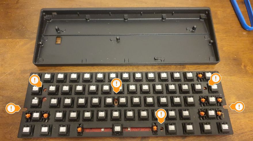
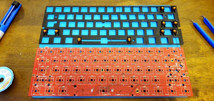
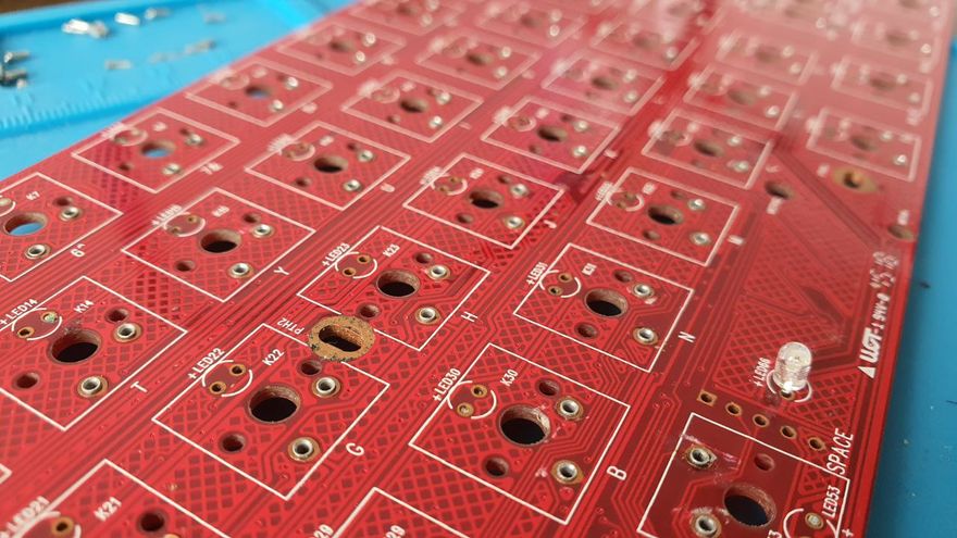
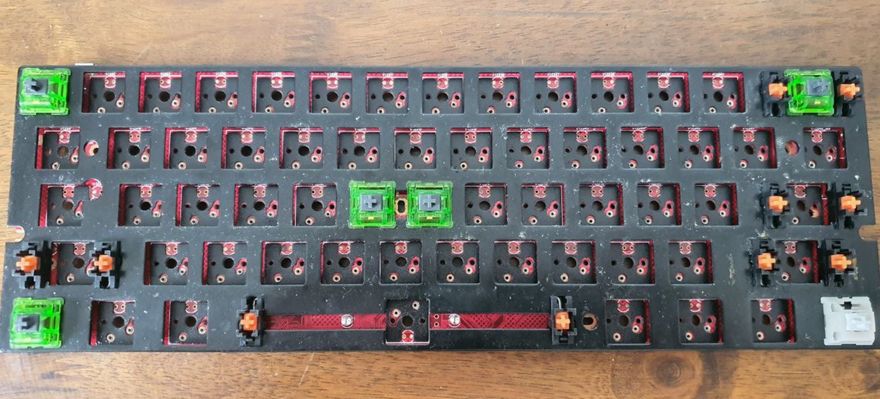
The PCB assembly is made up of two major components: the (black) metal plate where the switches secure themselves onto, and the (red) PCB underneath where the switches are soldered onto. The two pieces are only secured to each other by the switches themselves being soldered onto the PCB — so to separate them, we'll have to desolder all of the switches one by one. That would be 61 switches to desolder.
Desoldering
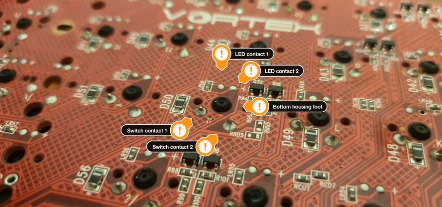
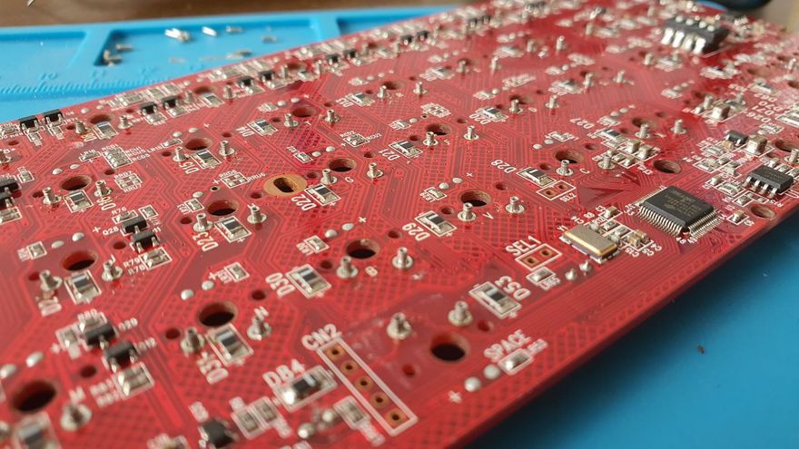
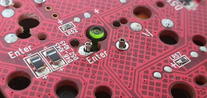
Switches are soldered on the underside of the PCB.
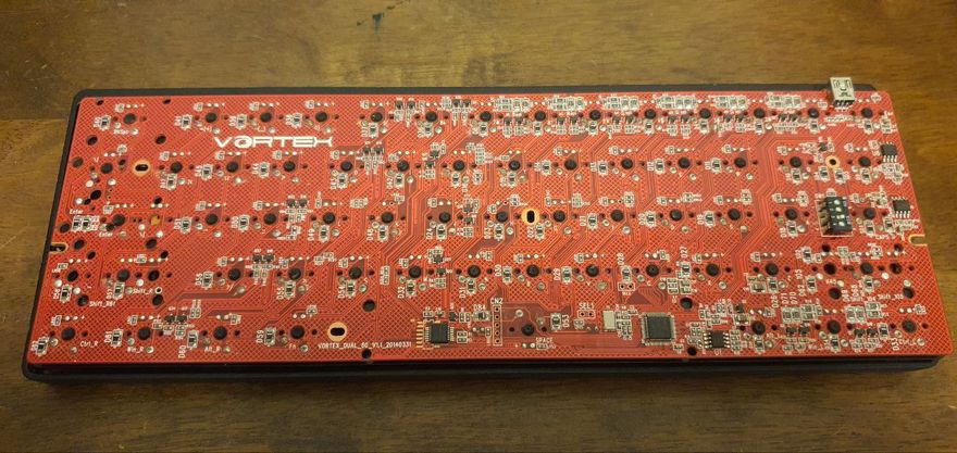
Each switch will have two solder points that will need to be desoldered. I didn't have an RGB Pok3r (so my switches didn't have LEDs), but an RGB Pok3r would also have solder points for the LEDs that will need to be removed. Look for each switch's bottom housing foot (the stem that is under each switch), and the switch contacts will be easy to identify.
Note that even on a non-RGB Pok3r like mine, the Caps Lock switch will have an LED mounted anyway, so that will also have to be removed.
I used a desoldering pump to get most of the solder out of the PCB, and desoldering wick to clean up what the pump couldn't suck out. The wick is really great for keeping the contact points as clean as possible for later as well.
Once a switch has been cleanly desoldered, you should be able to easily pull it out using a switch puller.
Once all the switches have been removed, the plate and PCB will separate. This would be a good time to clean the components. Mine had a lot of dirt and dead skin that had accumulated over the last seven years!
Hotswap sockets
These days, custom keyboards can be fitted with hotswap sockets that are simple to install on a PCB. The Pok3r PCB is not particularly made to accommodate these kinds of hotswap sockets however, so we can't use them unfortunately.
There's a few options that we can use — I personally used holtites so that I didn't have to solder them onto the board anymore. Another common alternative is mill-max sockets, which would need soldering.
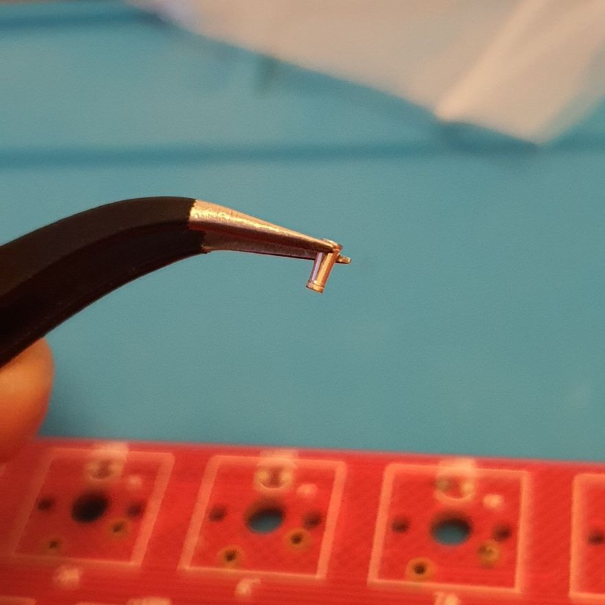
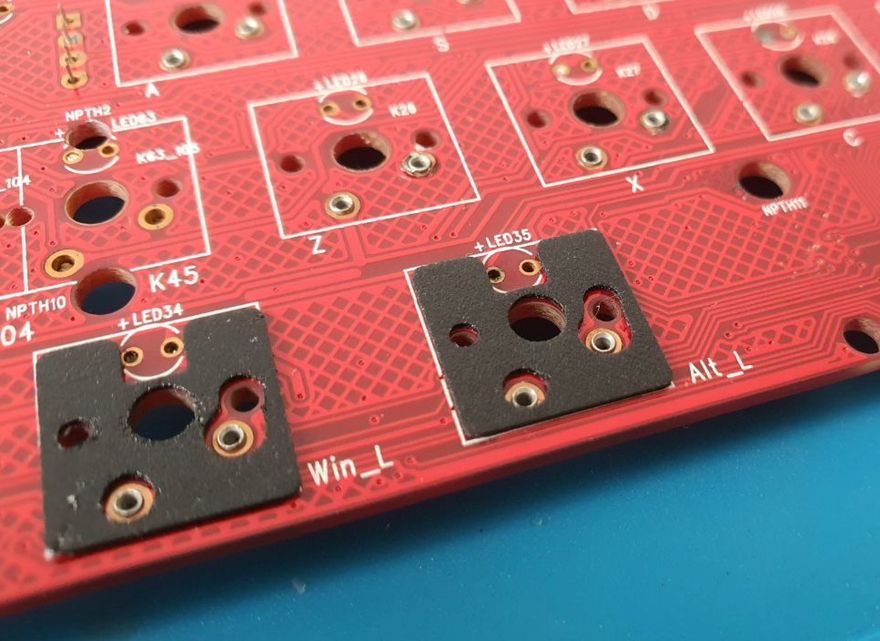
Holtites are really small and very easy to lose if mishandled. I used pointy-tip tweezers to put them into the right PCB sockets by "poking" a tip into a holtite, then using that to position into the hole. Occasionally, I'd use a pair of long nose pliers to hold the holtite in place inside the socket as I removed it from the tweezers.
To secure holtites into place, you'll need to heat them up with a soldering iron as you push them down into the hole. The heat makes them more malleable and will let them find a better fit in the socket. I used a blunt tip for my soldering iron to do this so that I can more evenly provide force into the push.
You don't need to solder the holtites into place at all.
Once secure in the holes, the holtites will protrude from the PCB by a small amount on the underside. On the top side, however, they should lie flush with the surface as much as possible. They should also feel fixed in place, and should not give when you try to push them out of the sockets.
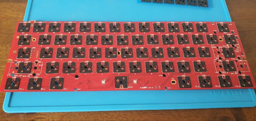
PE foam mod
One modification I did to my Corne v3 that I ended up really liking was to put some PE foam on the PCB for the switches to rest on. They're meant to provide a more snug fit for the switches once they're put in place, and helps minimize clatter when you type on them. In my case, they also seem to help give me a more thocky sound even with tactile switches, which I really like.
To make this easier for myself, I use pre-cut PE foam "stickers" that I can just stick onto the PCB directly, right where the switches would be. I've got enough left over from my Corne v3 build, so this works out nicely.
Re-assembly
Now that the holtites are in place (and we've got PE foam installed as well), we can put the keyboard back together.
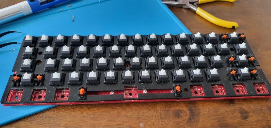
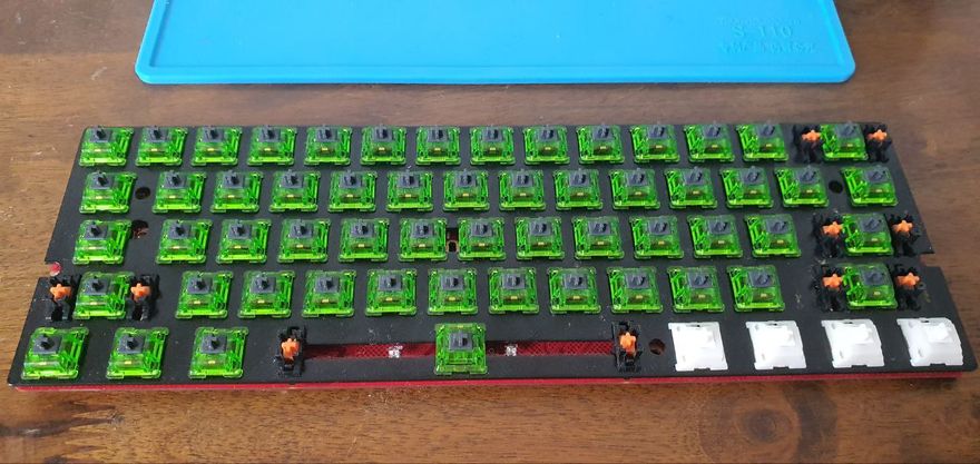
I started by placing switches in the corners of the plate, along with a couple in the very center. I then aligned this with the PCB and just placed the switches snug into place. With the holtites installed, you'll need to give each switch a firm push so that the contact pins fit into the sockets. The holtites should hold the switches in place firmly.
And, really, you just keep on going from there by putting your switch of choice back into the plate and PCB. Once you have all the switches in place, the plate and PCB will hold together on their own.
Just take care not to bend the switch contact pins are you push them into the sockets. If you do, take the switch out again and use a pair of pliers to straighten the pin out and try again.
Before you screw the PCB back into the case, you should test the keyboard first and make sure that all the keys are registering correctly.
Et voila
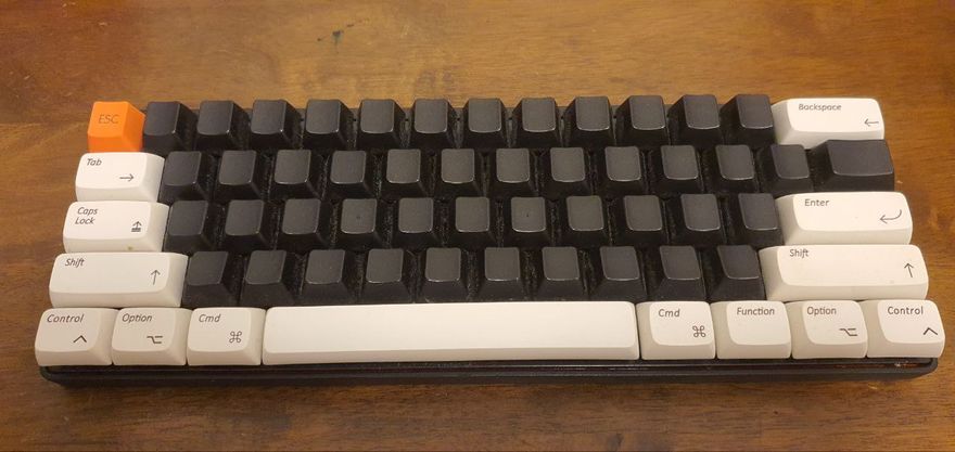
And there you have it. Just screw the PCB back into the case (again, there are six screw points!), and place your choice of keycaps, and the Pok3r is good as new. It's now been given a breath of fresh air, and is now much easier to swap switches around to try new stuff out in the future!